I. The Hook: A Visual History
Pull up a picture of a circuit board from a vintage 1970s analog TV, and you’ll see something that looks more like biology than technology. The copper traces sweep across the fiberglass in organic, spiderweb-like curves. They flow like rivers around mounting holes and gently branch out to connect components. It looks human. It looks grown.

Now, look at the DDR5 memory routing on a modern motherboard. The organic flow is gone, replaced by a brutalist cityscape of rigid, perfectly parallel lines. Every trace snaps to a strict 45-degree or 90-degree angle. It is the "Manhattanization" of electronics, a perfect, unyielding grid.
Why did electronics lose their organic, human touch? Why does every modern circuit board look like a city grid?
The shift wasn't just a stylistic choice. After reading through the history of the industry, I found it was dictated by the computational limitations of early software, the grid-bound algorithms of early CAD, and the unforgiving laws of high-speed digital physics. But as we push the boundaries of modern electronics, we are running into an uncomfortable truth: the rigid grid has reached its limits. To build the future, we have to teach computers how to draw the curves of the past.
II. The Rubylith Era: When PCBs Were Hand-Drawn
To understand why boards used to be curvy, you have to understand how they were made before CAD software took over. Engineers and draftsmen designed boards using light tables, massive sheets of translucent Mylar, and an X-Acto knife.
To connect two pads, a draftsman didn't click a mouse; they laid down rolls of black crepe tape and pre-cut pads and donuts from vendors like Bishop Graphics, with sheets of Rubylith masking film knife-cut for the larger copper areas. The artwork was made at 2x or 4x scale on Mylar and photographically reduced, which is part of why the linework could be so fluid. Crepe tape could be swept smoothly around pads and obstacles in one continuous motion; forcing a perfect 90-degree angle meant stopping, cutting the tape, overlapping a new piece, and pressing it down. The path of least resistance for the human hand was a curve.
At the time, the physics of the electronics didn't object. At the low frequencies of early radios and analog TVs, the electrons simply didn't care whether a trace curved or cornered. The human hand was free to draw whatever was easiest, and what was easiest was a curve.
III. The Grid Takes Over: Three Forces of Manhattanization
In the 1980s and 90s, the industry underwent a paradigm shift. The drafting tables were thrown out, replaced by desktop computers, and the sweeping curves vanished. The transition to the 45°/90° grid was forced by three distinct bottlenecks:
The Software Bottleneck: Early CAD systems simply lacked the horsepower to handle curves. Computing the clearances, design-rule checks, and intersections for arcs is far more expensive than doing the same math on straight line segments between X/Y coordinates. The grid was a necessary compromise for early CPUs.
The Algorithm Bottleneck: The classic autorouting algorithms were grid algorithms at their core. Lee's maze router (1961), the ancestor of nearly every autorouter since, works by flooding a grid of cells outward from the source pin. And with RAM scarce and expensive, representing the board as a coarse grid of cells was the only affordable data structure. The tools didn't just prefer the grid; they couldn't see anything else.
The Physics of Digital Speed: This was the final nail in the coffin for the curve. As electronics shifted from analog to gigahertz digital signals, traces stopped acting like simple wires and started acting like microwave transmission lines. To maintain signal integrity and strict impedance control, traces had to run perfectly parallel. Two straight lines on a 45-degree grid are perfectly equidistant; two organic curves inherently pinch and bow as they navigate around obstacles, changing the capacitance between them and destroying the high-speed signal.
IV. The Irony of the Autorouter: An Engineer's Perspective
I know exactly how deeply ingrained this grid paradigm is because I’ve spent most of my free time over the last few months trying to teach computers to route boards automatically. I'm building SnapCircuits, a text-to-PCB pipeline. Think Lovable, but for electronics: you describe the circuit you need, and the system designs the actual board. That goal changes the routing problem completely. A conventional autorouter that finishes 95% of a board is a useful assistant, because a human picks up the remaining nets. In a pipeline with no human in the loop, 95% is the same as failure. The router has to finish every board, every time, on its own.
Chasing that bar, I built three entirely different types of autorouters, and each taught me a different lesson about how machines "want" to think.
My first attempt was a heuristics router in TypeScript, modelled on the architecture of the open-source FreeRouting project but built for that zero-human-intervention goal. It was fast and rule-abiding, but incredibly rigid. Even after I replaced its routing grid with an exact-geometry, gridless substrate, the traces still marched at 45 and 90 degrees. I had removed the grid, but its angles were baked into every heuristic. It felt like writing a thousand "if/then" statements to reproduce Manhattan.
Next, I built a U-Net based Machine Learning router in Python, using a lattice-based decoder. I fed it thousands of human-routed boards, hoping the neural network would intuit the art of routing. But because the output was constrained to a pixel-like lattice grid, the results were still inherently blocky. The AI was trapped in the matrix.
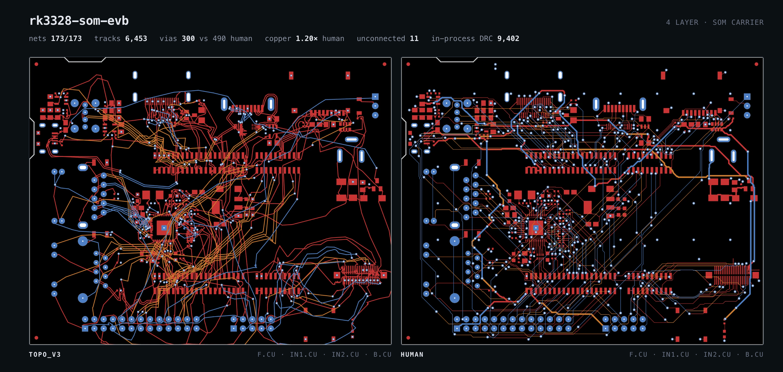
Finally, I threw out the grid entirely. I built a continuous-space topological router in Rust, based on Constrained Delaunay Triangulation (CDT) and Maley’s routing algorithms. Instead of thinking in X/Y coordinates, a topological router thinks in rubber bands. It figures out the relative topology of how traces should weave between pins, and then it mathematically "pulls" the traces tight.
When I first got the Rust CDT router working, I stared at the output in shock. The traces didn't look like a modern motherboard. They looked exactly like the 1970s analog TV.
Because the algorithm treats traces like elastic bands pulled tight around obstacles, the shortest path naturally forms straight lines tangent to arcs around the pins, effectively a belt wrapping around a pulley system. The mathematical truth is that the shortest, most efficient path between two points around an obstacle is exactly that: tangent lines and wrapping curves. The computer's purest math naturally wants to draw the curvy boards of the 1970s.
We have spent the last 30 years building incredibly complex push-and-shove algorithms just to force these natural, beautiful mathematical curves into unnatural Manhattan grids to satisfy legacy design rules.
V. The Modern Renaissance: The Return of the Curve
But today, the grid is breaking down. The cutting edge of modern hardware design is demanding the return of the curve, and tellingly, the factories were never the obstacle. Photolithography doesn't care whether a trace is straight or curved; it was the CAD toolchain that couldn't handle curves, and that toolchain is finally catching up.
Flex PCBs: Wearable electronics and foldable phones rely on flexible polyimide substrates. If you bend copper at a sharp angle, the mechanical stress concentrates at the corner, and the trace snaps. The IPC-2223 flex design standard explicitly calls for curved traces instead of cornered ones, to distribute physical stress.
5G and Radar: As we push into the tens of gigahertz for 5G, automotive radar, and satellite communications, the physics of the grid fail us. At those extreme frequencies, every corner becomes a measurable impedance discontinuity that reflects and radiates energy. This is why microwave designers have always mitered or curved their bends, and now the rest of the board has to follow. These frequencies demand smooth, curvilinear paths.
High Voltage and Power: In EV inverters and high-power electronics, 90-degree copper junctions generate thermal hotspots and current crowding. Electrons, like water, want to flow smoothly. Curves keep the system cool.
There is something beautifully circular about hardware design today. We are now using massive cloud compute, machine learning, and advanced continuous-space algorithms (like the Rust topological router I'm building today) to teach modern computers how to draw exactly like a human draftsman did with a roll of tape in 1975.
The grid was just a temporary detour. The future of the printed circuit board is curved.
I'm building all of this for SnapCircuits, a text-to-PCB pipeline where you describe a circuit and get a manufacturable board back. Some of the tools are already free to use on the site, and you can join the waitlist for the full pipeline there.
Sources & Further Reading
Section II, the Rubylith era
Section III, the grid takes over
Section IV, topological routing
Section V, the return of the curve
IPC-2223, Sectional Design Standard for Flexible/Rigid-Flex Printed Boards (summarized in JLCPCB's flex design guide): curved traces instead of cornered ones in bend areas, minimum bend radii, no stress concentrators.
Douville and James, "Experimental Study of Symmetric Microstrip Bends and Their Compensation", IEEE Transactions on Microwave Theory and Techniques, 1978. The empirical basis for mitering microwave bends, explained accessibly at Microwaves101.
Howard Johnson, "Who's Afraid of the Big Bad Bend?", EDN. Why corners are harmless at ordinary digital speeds but genuinely matter for microwave design, roughly a 1000x difference in sensitivity.